Control the aisle. Plan the whole system.
BOLEIN builds cold and hot aisle containment around the way your data hall is laid out. From cabinets and roof sections to doors, cable routes and controls, each part has a place in the project specification.
Containment is a room decision, not a cabinet accessory.
Airflow depends on more than where the racks stand. The roof must meet the aisle width; doors must work with the circulation route; gaps around cabinets, cable entries and overhead services need a coordinated plan. BOLEIN brings these components together so the enclosure system can be specified as one build.
Cold aisle or hot aisle?
Both approaches create a physical separation between equipment intake air and exhaust air. The choice comes from the room’s cooling architecture, return path, existing racks and installation constraints.
Keep supply air at the equipment intake.
Enclose the aisle facing the front of the racks. End doors and roof sections help define the path from the cooling supply to the server inlets. This is often considered when the cooling design delivers air into the aisle.
Design review: supply location, floor or overhead delivery, aisle width, door traffic and roof coordination.
Collect exhaust air behind the racks.
Enclose the aisle at the rear of the equipment and coordinate the warm-air return route with the room cooling design. Roof and door details depend on how exhaust air is taken back to the cooling system.
Design review: return-air path, overhead clearance, service conditions inside the aisle and fire-system requirements.
Containment hardware does not replace a cooling design. Final configuration should be coordinated with the facility’s airflow and fire protection plans.

Start with the cabinets. Finish every opening.
Cabinet alignment defines the aisle; roof modules and end doors complete its boundary. Cable entry, bridging panels and blanking pieces close the practical gaps that a clean rendering can hide.
- Cabinet row: height, width, depth, load and equipment access
- Roof: fixed and operable skylight sections to suit the design
- Ends: automatic sliding or manual door options
- Edges: end panels, infill and blanking panels around transitions
Every component has a job to do.
The exact bill of materials varies by room. These are the elements BOLEIN can discuss when turning a concept into a coordinated containment package.
Define the boundary
- Network cabinets19-inch enclosures, doors, side panels and mounting space.
- Fixed roof sectionsGlazed or solid roof areas placed to suit the aisle layout.
- Operable roof sectionsOpenable skylight modules where the project design calls for them.
- Blanking & infill panelsClose unused spaces and transitions around the row.
Make the aisle usable
- Automatic sliding doorsEnd-of-aisle access with a planned opening route.
- Manual door optionsAlternative entrance formats for the operating pattern.
- Alarm & displayAudible or visual alerts and status display options.
- Ambient lightingLighting integrated with the aisle design.
Coordinate what crosses it
- Top trunking & cable ladderOrganized overhead paths for data cabling.
- Fire control interface boxSpace and interface to coordinate with the approved fire strategy.
- Cable entry & sealingRoute services while managing openings in the boundary.
- Cabinet accessoriesPDU, shelves and mounting rails selected per rack.
Inside a 7.5 m aisle: 26 cabinets and four precision cooling units.
This project combined a 26-cabinet row with four precision air-conditioning units inside the aisle. The detail that makes it more than a standard rack layout is the enclosure around it: three 600 mm roof-module types, including a fixed metal section made to wrap around a column, plus a controlled sliding entrance and the cable, fire-control and display components specified for the aisle.
The aisle is built around the equipment.
Twenty-six 47U floor-standing cabinets form the row. The specification also calls for 52 side doors in 1.2 mm sheet metal and four precision air-conditioning units inside the 7.5 m aisle.
One roof, three kinds of module.
The 600 mm roof package includes sheet-metal fixed sections, acrylic operable skylights and sheet-metal fixed sections formed around a column. Aisle blanking panels complete the listed enclosure scope.
More than an end door.
The automatic sliding door set includes a door housing and standard access control. Ambient lighting, a display screen, fire control box and M-type cable trunking are part of the project configuration.
Configuration at a glance
Project data provided by BOLEIN. The shelf and rails are optional. The separate rendering below illustrates a containment concept and does not depict this project.
A hot aisle layout built around changing row ends.
BOLEIN supplied a hot-aisle containment package for a data center with several row-end layouts. Different end-door arrangements, cabinet infill and an overhead cable route around a building column were brought into one coordinated package.
One end configuration uses a 3.6 m automatic double sliding-door assembly for a 1.2 m aisle passage. Other ends use different door and infill modules, matched to the cabinet rows they close.
Doors matched to each end.
The design includes automatic sliding-door variants with transparent panels, access-control provisions and safety sensors. The end assemblies vary with the row layout.
Enclosure around real obstructions.
Different panel widths close the spaces beside cabinet rows. A purpose-designed cable tray passes around a structural column while maintaining the overhead route.
Control planned into the package.
The specified control boxes provide a 12 V fire-signal interface and two-color ambient-light control. The drawings also show access-control and exit-button positions at the doors.
See the system before final specification.
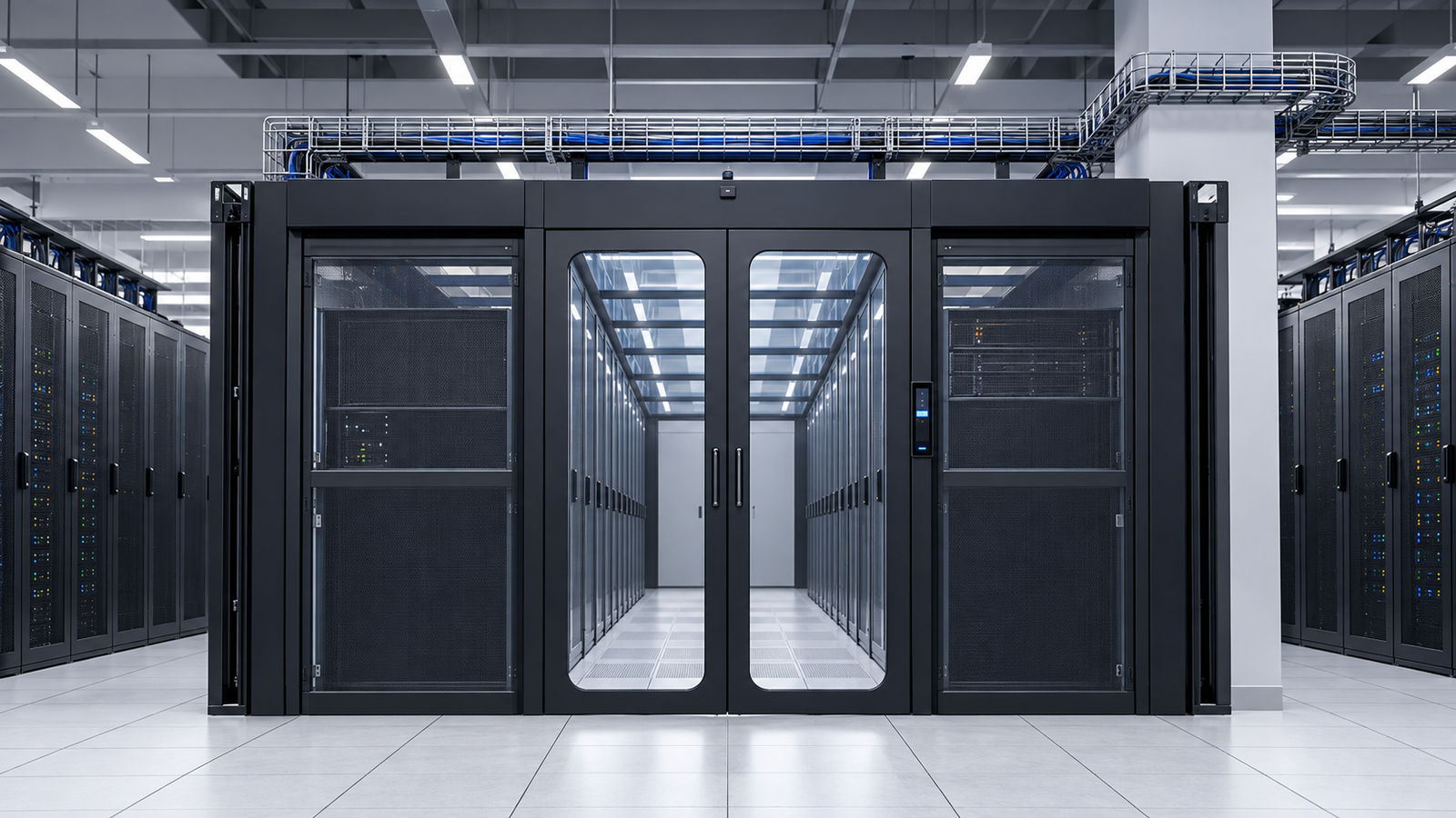
A dual-row cold aisle brings cabinet alignment, overhead cable routing, fixed and glazed roof sections, and sliding end doors into one coordinated layout. The concept makes it easier to review access and service paths before detailed dimensions and interfaces are confirmed.
For a live project, BOLEIN can work from your rack schedule and room drawings to discuss module layout and accessory selection.
Prepare a Project Brief →
What has to be decided before a quotation?
A useful containment quote is tied to a room and a rack plan. These inputs determine whether the doors, roof, services and controls can be specified coherently.
Floor plan & clearances
Room dimensions, column positions, ceiling height, obstructions and access route.
Row schedule
Rack count, height, width, depth, equipment load and any unequal-height units.
Supply & return
Cold or hot aisle concept, floor or overhead supply, return path and target aisle width.
Doors, roof & services
Door mode, fixed or operable roof, cable ladder, lighting, alarm, display and fire interface.
If some details are still open, send the current drawing and mark the unknowns. The next step is to review the configuration with your project team.
From fabricated frame to installed aisle.
The system must work on the shop floor and in the data hall. These views show cabinet assembly, production capacity and a completed aisle environment.


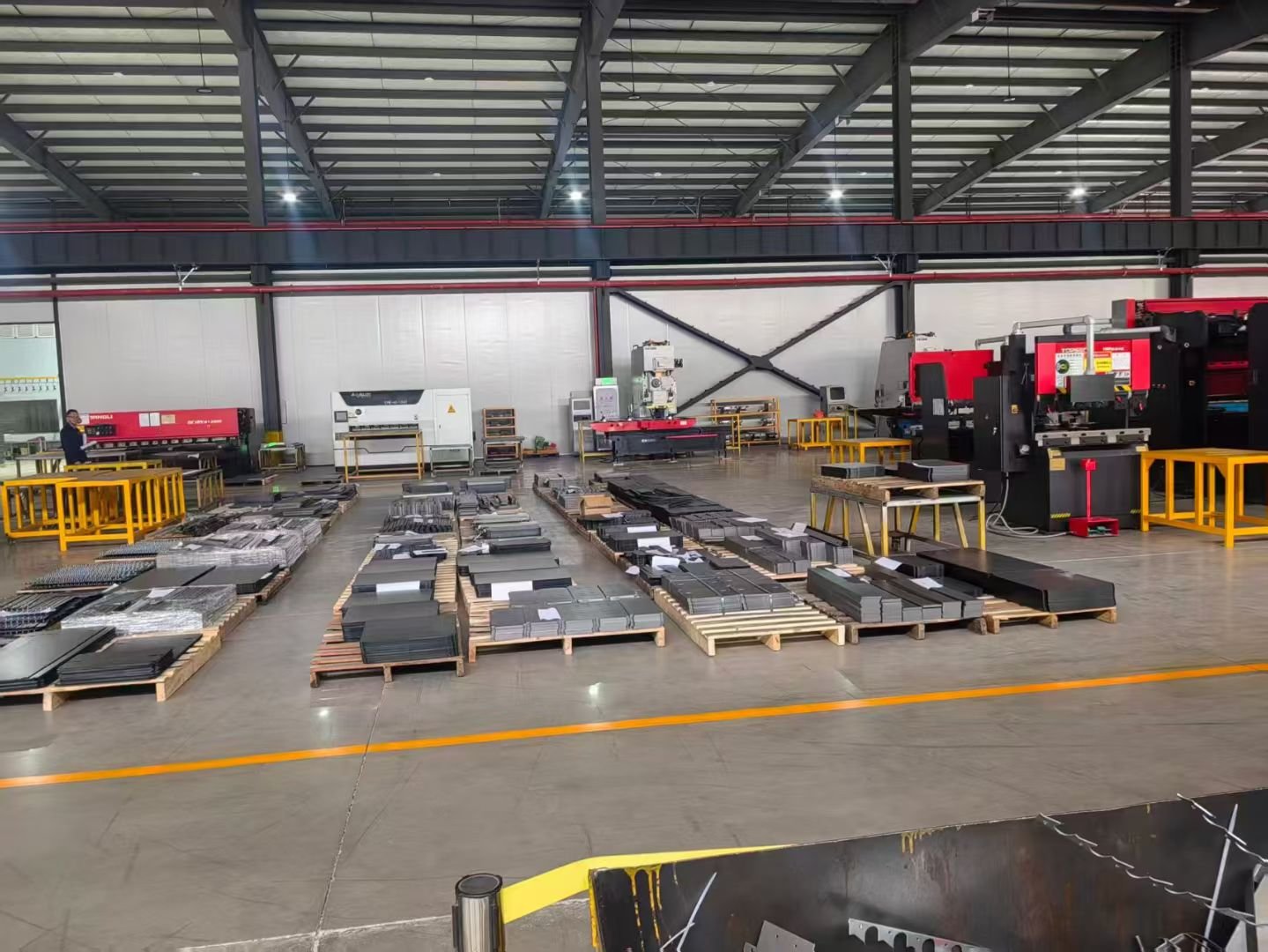
Complete the infrastructure around the containment.
The aisle package connects to the rack-level choices your operators will use every day.
19-inch enclosures
Choose equipment space, door and panel format, rail positions and static load to suit each row. Confirm the cabinet configuration against the equipment schedule and access plan.
PDU options
Specify the PDU input, outlet type, mounting format and quantity for each rack. Custom intelligent configurations can be discussed when monitoring or control is required.
Shelves, rails & cable paths
Specify mounting rails, shelves, cable management and blanking pieces with each rack so accessories fit the equipment and remain accessible after installation.
Move from room drawing to a buildable list.
Share the room
Send layout, rack schedule and cooling concept.
Set the aisle
Confirm containment type, dimensions and door access.
Coordinate interfaces
Review roof, cable routes, controls and accessories.
Confirm the package
Agree the component list and project-specific specification.
Before the first drawing review.
Can BOLEIN supply both cold and hot aisle containment?
Yes. The enclosure strategy, roof and return path are discussed against the facility cooling concept.
Can the roof combine fixed and operable sections?
Yes. The module plan depends on aisle length, overhead services and fire-system coordination.
Are automatic sliding doors available?
Yes. Automatic and manual door formats can be considered; final access and control details are project-specific.
Can controls and lighting be included?
Alarm, ambient lighting, displays and fire control interface boxes can be discussed as part of the system configuration.
What if the cabinet heights are different?
Send the rack schedule and elevations. Transitions and infill should be reviewed before the roof and panel list is fixed.
Can PDUs and rack accessories be quoted together?
Yes. Include outlet type, input, mounting location, shelf loads and rail requirements in the project list.
Bring us the room. We will discuss the aisle.
Send your current layout, rack count and cooling concept. Even an early-stage drawing is enough to start identifying the roof, door, cable and control decisions that belong in the scope.
Room plan
Dimensions, elevations, ceiling and access route.
Rack schedule
Count, sizes, load and accessory requirements.
Cooling & interfaces
Supply, return, doors, roof, alarm and fire coordination.